Stress Analysis of an L-Bracket + Topology Optimization
Purpose: Topology optimization is a shape optimization method that takes the conditions, loads, and constraints from the engineer and uses an algorithmic model to optimize the design within these user selected parameters. Topology optimization can be used to maximize the performance and efficiency of a specific design by removing unnecessary material as it relates to the engineers criteria for that particular objective i.e thermal, resonance, weight reduction. In this example, I perform topology optimization on an L-Bracket with the main purpose of making it cheaper to manufacture, while still being able to withstand the forces it will be subjected to during use.
Problem: I could not find a problem so I created my own below. Assume we had an L-Bracket made of structural steel that is fixed on one hole while the other faces a 25 N bearing load in the negative x-direction.
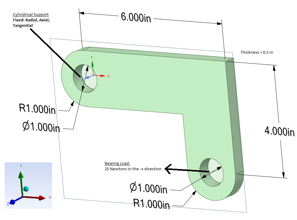
Hypothetical L-Bracket problem
ANSYS Mechanical Stress Simulation
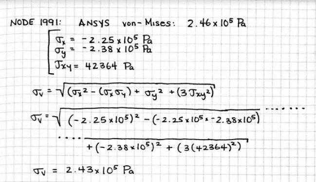
Verification & Validation: To validate, I perform a quick hand calculation on 1 of the >10,000 nodes in my mesh with a given sigma_x, sigma_y, shear_xy and compare it with the von-Mises calculated by ANSYS. I receive 2.43e5 Pa for my von-Mises, within rounding error of ANSYS’ calculated 2.46e5 Pa.
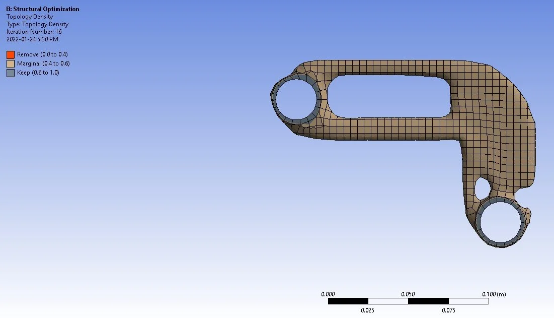
Results after structural optimization ~50% weight reduction

Original L-Bracket

Modified L-Bracket with a more distributed stress gradient
Conclusion: It’s really satisfying to feed a part into ANSYS with all of the conditions, loads, constraints of the design and watch the algorithm generate these extremely complex looking 3D geometries. It was also cool to watch the algorithm determine the radii of the internal and external fillets to best distribute the stress. It then becomes the engineers problem to know their companies manufacturing process in-depth to decide which material of the part is worth removing for the sake of manufacturability, as the more complex a geometry is the more expensive it would be to produce — which is why I omitted many of the contours and smaller cut-outs produced by the topology optimization. As the problem is more illustrative than scientific, I would not put a high degree of confidence in the values received without undergoing the tedious task of mesh optimization. If we take the values from our default ANSYS mesh vis à vis, we reduce a large chunk of material and the factor of safety drops marginally from 318 to 294, meaning the bracket would still be able to withstand a bearing force just shy of ~300 times greater than what it is currently being subjected to.

A beautiful topology optimized electric motorcycle chassis by the engineers at Airbus APWorks’ “Light Rider”. An acceleration speed of 0-45 km/hr in 3 seconds with a top speed of 80 km/hr. Total weight slightly less than an 80 lb dumbbell (The frame itself is 13 lbs)
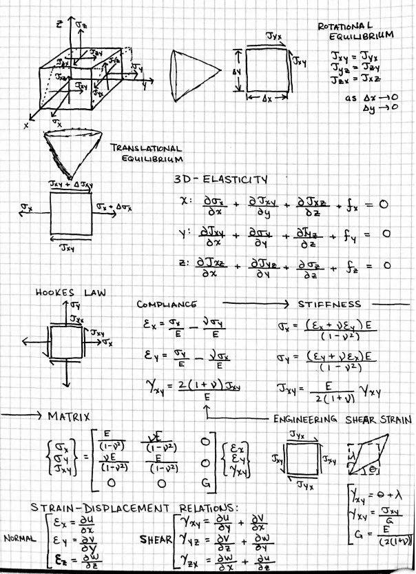
Development of the stiffness matrix. How ANSYS works under-the-hood to convert the differential equation into an algebraic system of equations solvable by the computer. Credits to Prof. Bhaskaran (Cornell University)